
Sifting through a fleet of sound optionsEngineering sound proofing solutions for boat means understanding the unique needs and specific construction of each vessel. The appropriate sound proofing solutions for cruisers and sport fishers will be significantly different than those Soundown will recommend for large yachts or commercial vessels. Even similar vessels may have different needs based on the arrangement of machinery spaces and accommodations or the type of construction. This section of the website includes products, systems, and general vessel solutions. If you are looking for a specific item the products section will provide general product information and performance details. For specific systems such as marine exhaust, quiet drive lines, floated interiors (and many others) the systems/applications section will provide in depth information and construction details. The Vessel Solutions section offers a wide range of treatments that apply to specific categories of boats from runabouts to large yachts and commercial vessels. Whether you are looking for simple solutions that can be applied to your current vessel, undertaking a major refit, or building a new vessel Soundown has the sound proofing materials and experienced support staff to reach your noise control objectives. Related Article: Filling the holes, muffling the machinery, by Eric Sorensen, Soundings |
|||
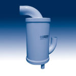
Products |
|||
 |
 |
 |
 |
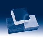
Systems |
|||
 |
 |
 |
 |
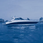
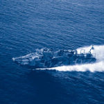
Vessels |
|||
 |
 |
 |
|